Keywords: router, SOHO router, switch, level 2 switch, ethernet hub, ethernet port, NIC, IP address, MAC address, DHCP server, Local Area Network, LAN, subnet mask, subnetting, ARP tables, TCP/IP packet, datagram, frame, RJ45, networking, network hardware, network device
Network hardware: routers and switches
We have defined the Internet as a “network of networks” of connected devices. Let’s explore this concept further.
Switches
Most switches manage TCP/IP packets at the frame (MAC address, OSI layer 2) level. For this reason, they can also be referred to as “level 2 switches” (level 3 switches also exist, however they are beyond the scope of this discussion, which will only refer to the classical level 2 switches). In other words, switches know nothing about IP addresses and only manage packets traffic by using MAC addresses. This may be obscure for now, but will become clear in the packet journey across networks part of this section below. Hang tight.
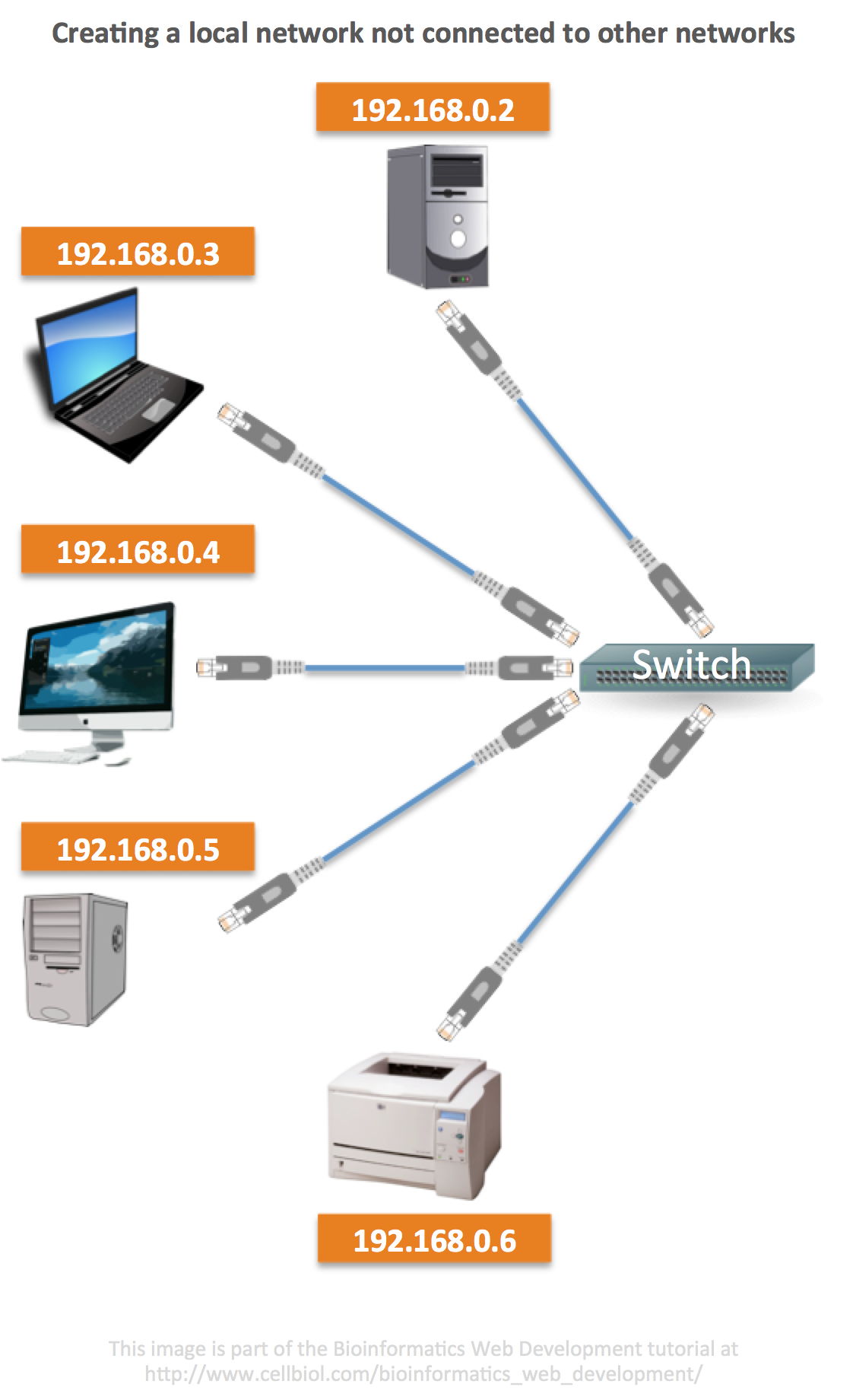
We could build a simple standalone network, such as a Local Area Network (LAN) of computers and other connected devices (printers, network drives, network cameras, connected toasters, connected light bulbs etc…) with just a switch and a few ethernet cables (and/or a WiFi access point if the devices have wireless cards).
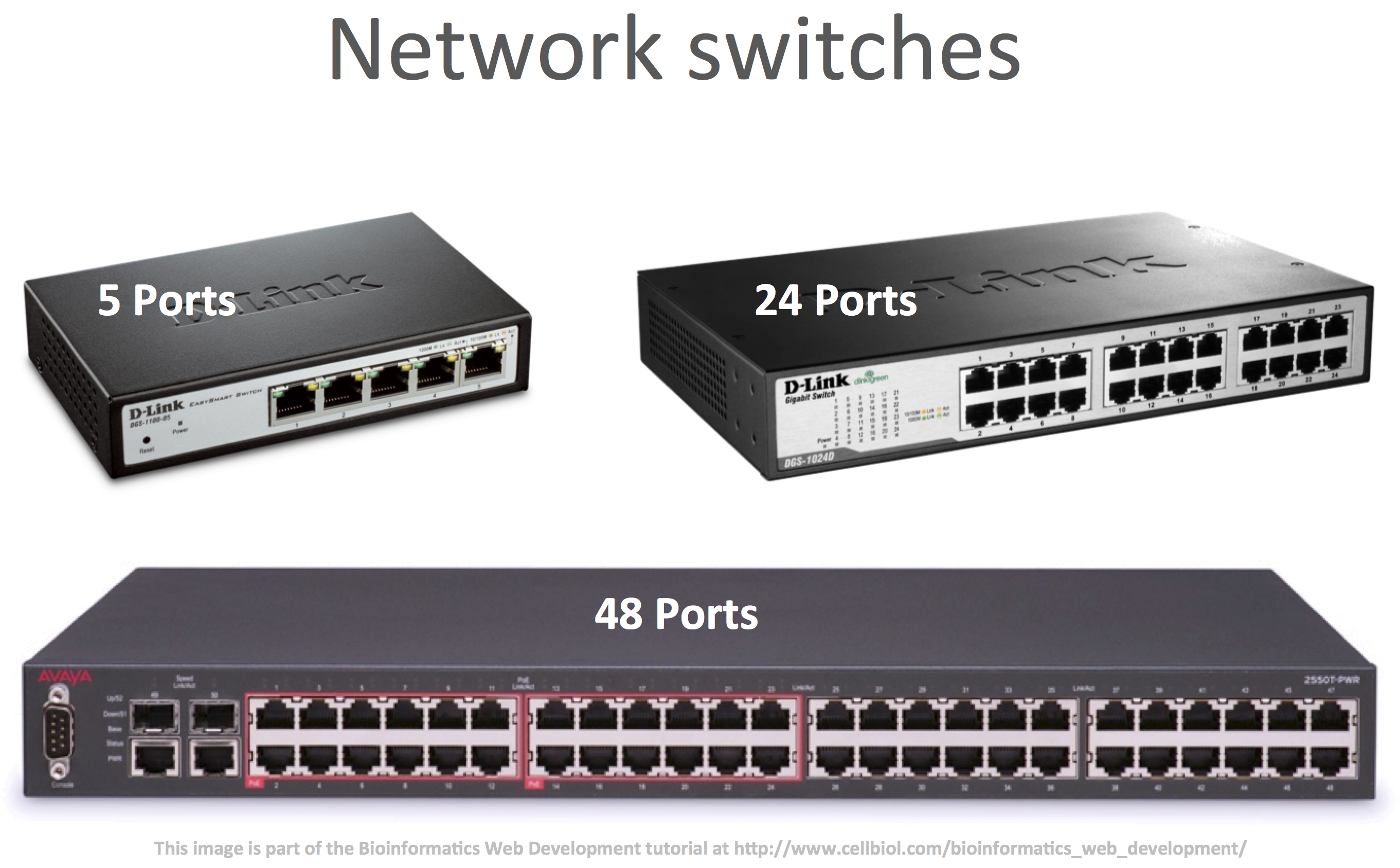
We would connect all the devices to the switch through the cables.
For an automatic assignment of network configuration parameters (IP address, subnet mask) on connection of the devices to the network, we could then install a DHCP server in one of the computers. We could still manage without a DHCP server by configuring the network settings of each device manually.
The topic of IP addresses, IP classes and subnet masks is complex and addressing it comprehensively is beyond the scope of this book. For the sake of this discussion let’s just say that the network mask defines, within an IP address, which part is reserved to the network identification (this part of the IP address is called the network prefix) and which part is available for identifying the devices on the local network (the hypothetical LAN for this example). This second part of the IP address is called the host part. Thanks to subnet mask, the host number part of the IP address can further subdivided in a subnet number plus the host number. This operation is referred to as subnetting and can be very useful when a unique network that must comprise more than 255 devices is needed, which is frequent in large organizations.
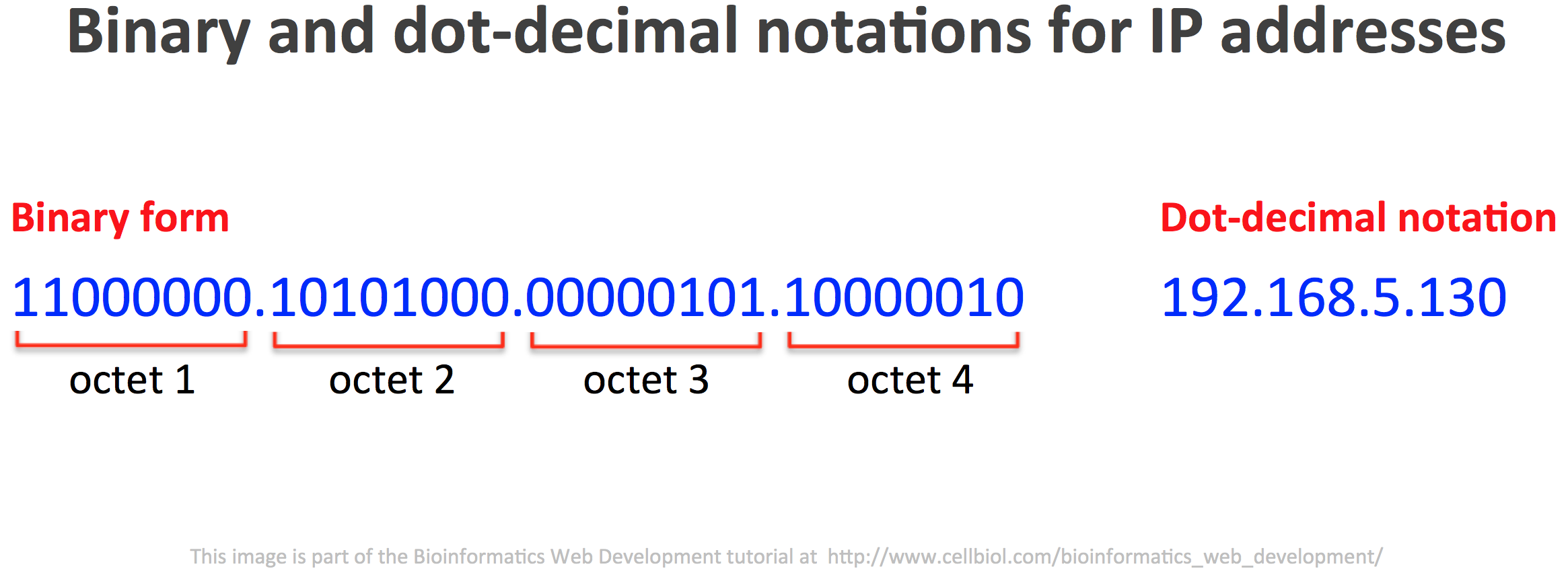
The subnet mask 255.255.255.0 is associated to small local networks of up to 255 devices each. It indicates that the first 24 bits of the IP address are reserved to the network prefix, while the last 8 bits (IPv4 IP addresses are 32 bits numbers) are reserved for the hosts. For this reason, a network associated with this IP range:
192.168.0.0-255
can be referred to as
192.168.0.0/24
where 24 indicates that the first 24 bits of the IP are reserved to the network prefix. This is called the CIDR notation.
In summary, with a subnet mask of 255.255.255.0, the 192.168.0 part of the IP addresses would identify the network, while the host part, that can contain numbers from 0 to 255, would refer to each individual device of the LAN. Valid IP addresses for this range could be for example 192.168.0.22 or 192.168.0.45.
Addresses in the range 192.168.1.0/24 would then be on different network (the one with a 192.168.1 network prefix, as opposed to 192.168.0).
We could connect up to 255 devices to a switch (if it had enough connection slots), assign each one an IP address in the same range, for instance 192.168.0.0-255 and a subnet mask of 255.255.255.0 and there we have a working local network in which each device can communicate with the others.
Routers
Routers manage TCP/IP packets at the datagram (IP, OSI layer 3) level.
You may have noticed that in our “standalone network” building above, the word “router” was not mentioned. Indeed, a router is a device needed to connect networks, to establish a “route” between two or more networks. For each of the networks to be connected, the router needs a dedicated NIC with an IP address in the range of the network it is associated with. In order to build a standalone network, a router is therefore not needed. If instead we wish to connect a local network to another network, be it another local network or the Internet, we do need a router.
While a router could be as simple as a small inexpensive PC with two NICs, for example two ethernet ports, such as the one shown in the figure below,
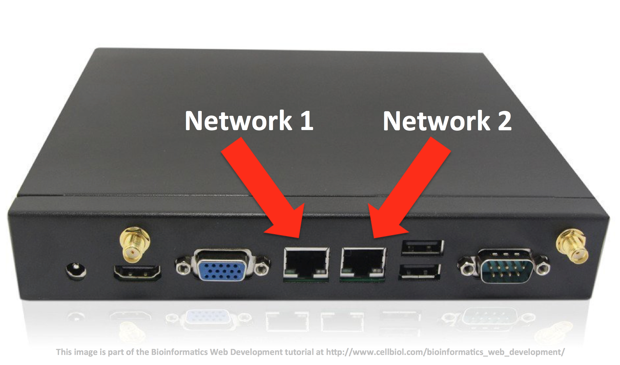
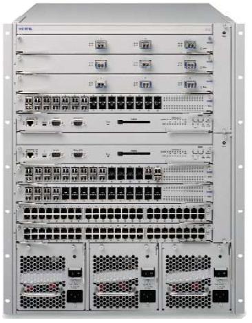
other router models are big, heavy, expensive and somewhat intimidating devices that lie at the core of the Internet, regulating and shaping the word’s exchange of data within big organizations, whole countries or across nations.
SOHO routers
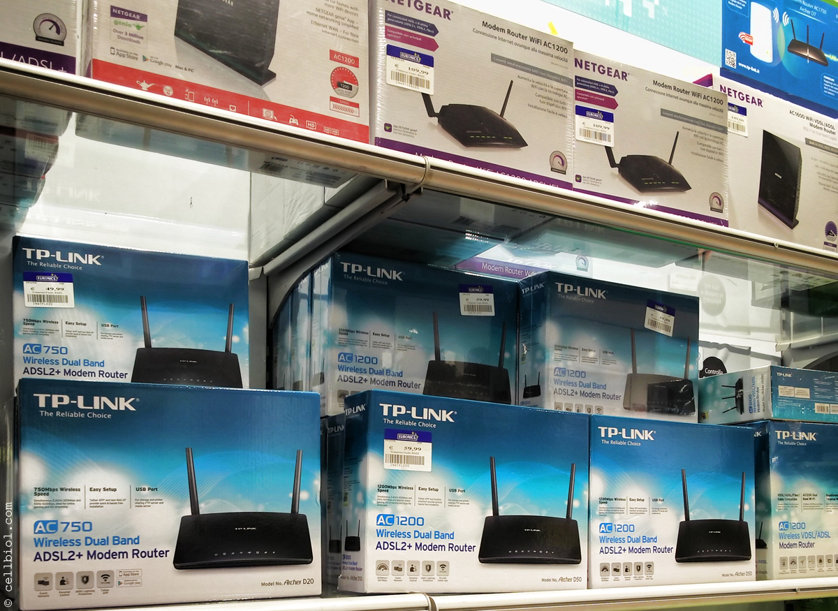
The concept that a router is not needed to build a local network may be confusing as home users with an inclination toward technology are now well aware that they can use one of those commercial “routers”, that can be bought for 20-200$/€ (or more!) in every consumer electronics store, to build an local network with computers, printers, cameras etc…
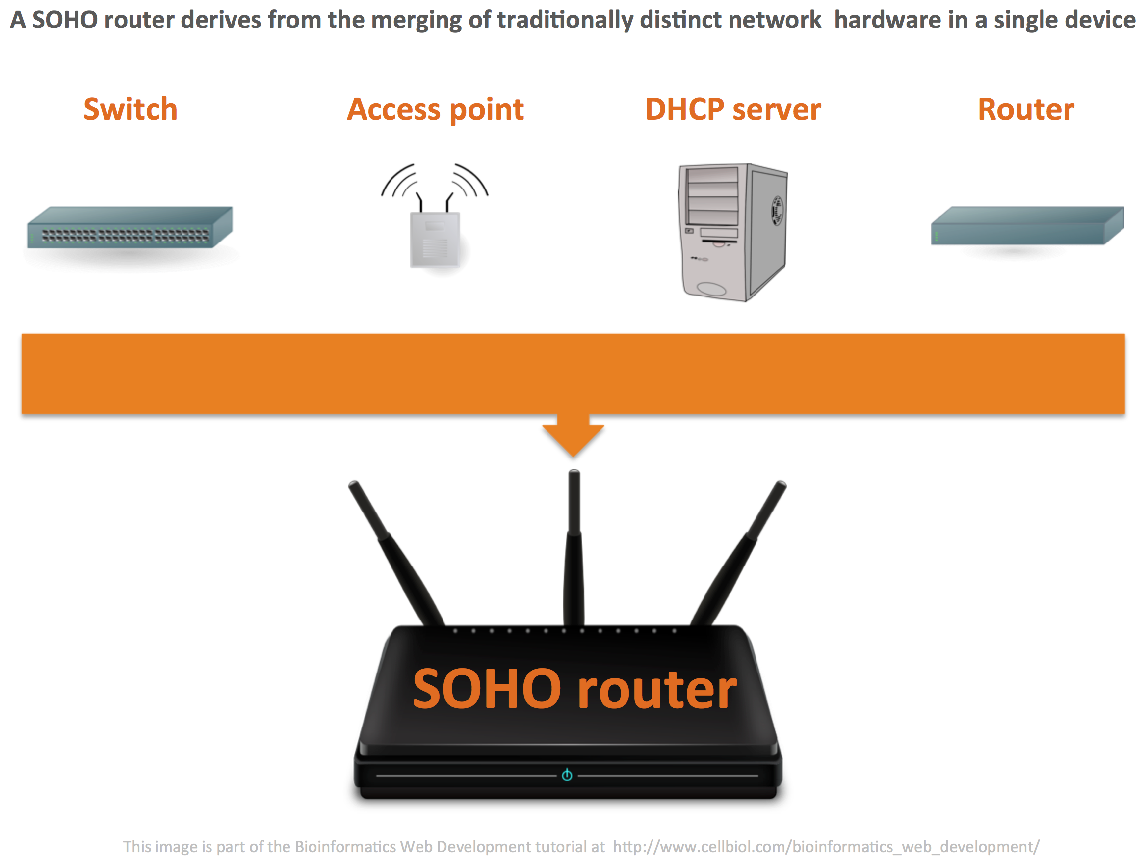
One reason for the confusion is that the routers home users are familiar with, technically known as “SOHO” (Small Office Home Office) routers, are not routers in the pure networking sense of the term that was outlined above. A SOHO router merges several traditionally distinct network devices with different functions, namely a switch, a wireless access point, a DHCP server and, indeed, a router, into a single hardware device. You know know, thanks to what was discussed above, that while building your home/local network, you are actually using the switch, access point and DHCP server parts of the SOHO device. The router part only comes into play when you want to connect your home/local network to the Internet.
We know that network traffic based on the TCP/IP standard is made by packets, as discussed in the previous section of this chapter. We can therefore define a router as a “device that forwards packets through computer networks” (ref: Wikipedia).
Following the journey of a TCP/IP packet across networks
In order to follow the journey of a TCP/IP packet from one computer to another located on a different network, across network hardware, let us consider two networks connected by a router, such as the example in the next figure.
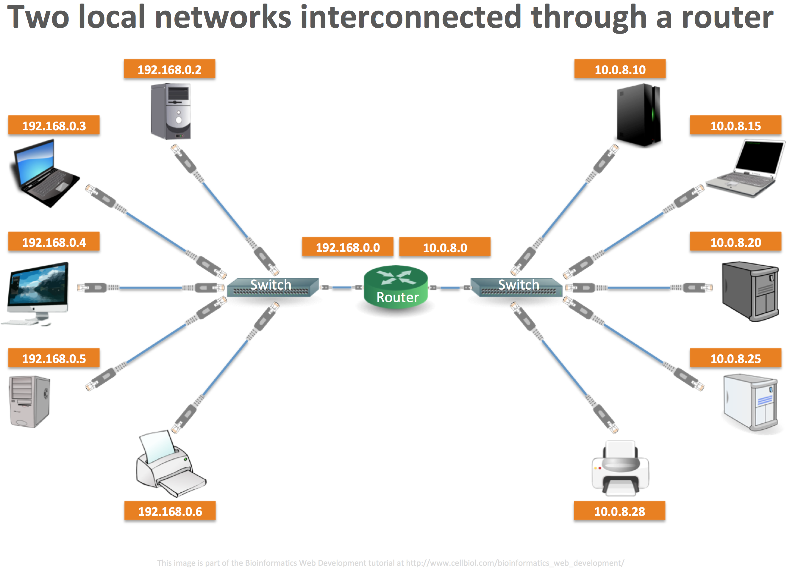
Let us now simplify the picture and retain just one computer from network 1, the source computer for our packet, and one computer from network 2, the destination computer.
The journey of the packet is schematized in the next figure. Please click on it for a larger version.
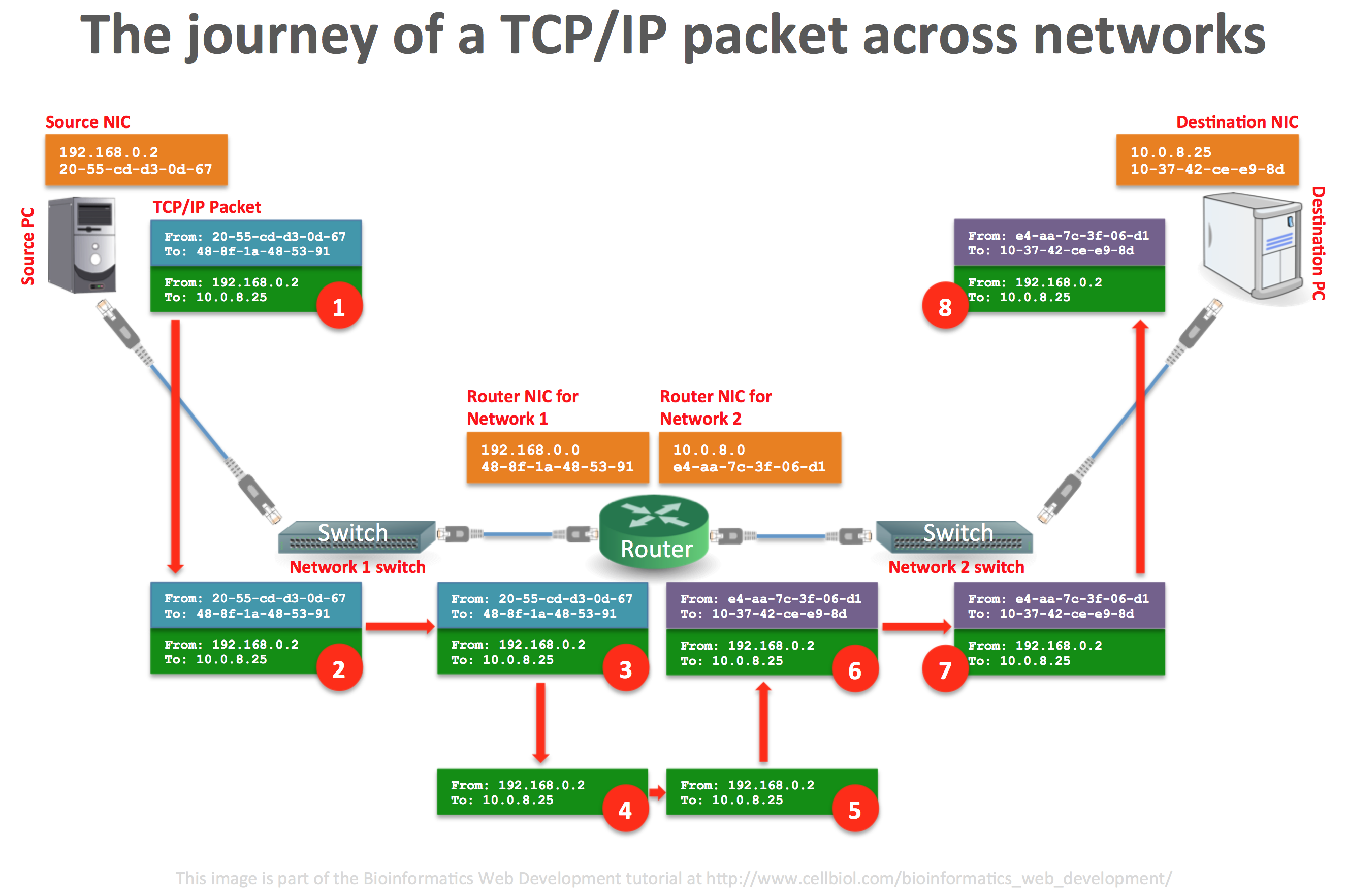
Let’s analyse what happens in the figure above.
1) A data packet was created on OSI layer 4 (not shown in the packet representation in the figure), then encapsulated into a datagram, with source and destination IPs (shown) and finally in a frame, with source and destination MAC addresses (shown). We have already discussed this TCP/IP encapsulation procedure in the previous section.
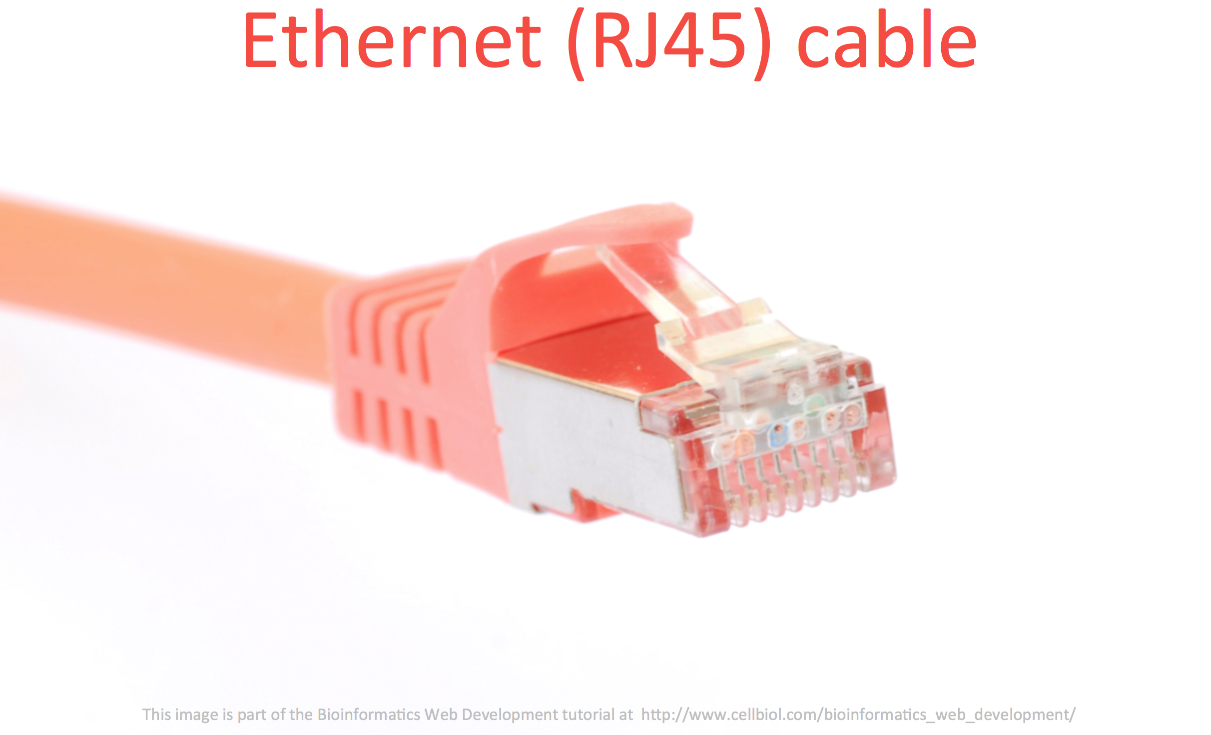
2) The packet reaches the network switch by traveling in the physical layer (OSI layer 1, the network ethernet cable). The switch reads the destination MAC address from the frame. If the packet destination is inside the network, the packet is delivered to destination, there was no need to read datagram (IP addresses) information, and transmission is over. No router needed. If instead the destination device is outside of the local network, the destination MAC address is the one of the gateway (the router).
Nota bene: The switch knows which one of his ports is associated with which MAC address and only forward the packet to the correct port. Incidentally, this is what differentiates switches from ethernet hubs (which at first sight look very similar to switches with their array of ethernet ports), as hubs just forward every packet to every port (this is called broadcasting), leaving to each connected device the task of figuring out if the packet was destined to them or not. Switches therefore optimize the traffic, while hubs are highly inefficient and have limited speed, for this very reason.
3) The packet reaches the router’s NIC interface associated to the current network.
4) Here comes the routing part. The router strips the frame from the packet, as it is not needed anymore, exposing layer 3 (IP addresses) information. This is what the router works with.
5) The packet is transferred to the NIC associated with the destination network. In the figure we only have two networks. However the router may have more than two NICs and be associated with more than two networks.
6) By looking into his ARP tables, that allow the resolution of logical addresses (IP addresses) to physical addresses (MAC addresses), the router encapsulates the datagram into a new frame. So now the router’s job is over and it’s the switch turn again to manage the packet.
7) The packet with the brand new frame gets to the switch belonging to the second network, that transfers it to the port corresponding to the MAC address of the destination computer.
8) The packet has reached the intended destination
The description of the flow of events associated with the journey of a TCP/IP packet across networks, in this format, was inspired by the following “Networking crash course” video by Canadian engineer Mark Fourneaux. You may want to watch it carefully as it is extremely well done, easy to follow and informative. It is part of a comprehensive video series on setting up a router with the pfSense software, a useful and empowering exercise to do by the way. Thank you Mark for sharing this on the Internet!
A typical task you may want to perform is to set up a small LAN at home or in the lab. This is the topic we will discuss in the next section.
Switch: http://www.clker.com/clipart-1817.html
Router: http://www.clker.com/clipart-1882.htmDHCP server icon: http://www.clker.com/clipart-11285.htm
Router: http://www.clker.com/clipart-16348.html
Access point: http://www.clker.com/clipart-access-point-device.html
SOHO router icon: http://www.clker.com/clipart-wireless-router-2.html
RJ45 connector: http://www.clker.com/clipart-ethernet-plug-network-straight-connector-rj-45-lan.html
Laptop: http://www.clker.com/clipart-14767.html
Laptop: http://www.clker.com/clipart-1810.html
iMac: http://www.clker.com/clipart-the-new-27-imac-without-white-bg.html
Computer: http://www.clker.com/clipart-10431.html
Computer: http://www.clker.com/clipart-1902.html
Computer: http://www.clker.com/clipart-25693.html
Computer: http://www.clker.com/clipart-1826.html
Printer: http://www.clker.com/clipart-3664.html
Printer: http://www.clker.com/clipart-3654.html
Chapter Sections
[pagelist include=”36″]
[siblings]